|
|
|
- Contact
us Other instruments: - Measures
-
Scales |


|
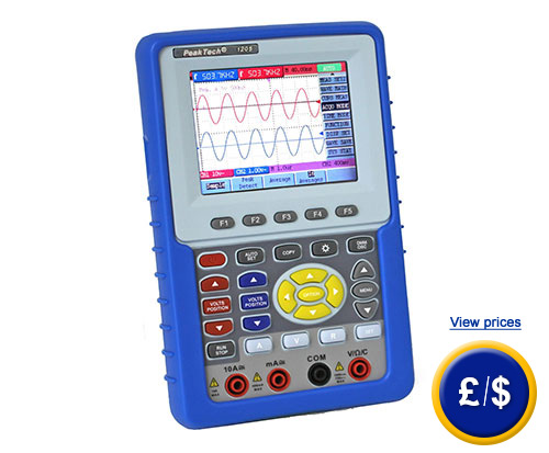
Oscilloscope (handheld) PKT-1195 |
|||
|
The handheld Oscilloscope PKT-1195 is a device that combines a 2 channel oscilloscope data logger and TRMS multimeter. This Oscilloscopes PKT-1195 is the ideal device for many purposes. The creative and simple design of the Oscilloscope PKT-1195 makes it easy to use. The colour TFT 3.8" screen of the Oscilloscope PKT-1195 (resolution: 320 x 240 pixels and 65535 colours) can display curves easily. To allow mobile work, the handheld oscilloscope has a lithium-ion battery which ensures continuous measurements due to its long battery life. Thus, these devices are ideal for measurements in the workplace or on site. Due to the automatic range adjustment and automatic configuration of the handheld oscilloscope, you can work with the handheld oscilloscope quickly and safely. The measurement values of the Oscilloscope PKT-1195 can be stored directly onto USB stick. The integrated meter of the handheld oscilloscope has all the standard functions and it is also equipped to measure capacity. If you have any questions about the Oscilloscope PKT-1195, see the technical data below or contact us. Our engineers and technicians will advice you on the handheld oscilloscope or any other product in the field of regulation and control, measuring instruments and scales or balances. |
|||
|
|
|||
|
|
|||
|
- USB port - Portable USB pen connection to store data - Automatic setting - 20 MHz or 100 MHz bandwidth (depending on the model) |
- Measures capacity - Ion-lithium or net component power supply - Real effective value multimeter (TRMS) - 6000 points by channel current time memory |
||
|
Technical specifications |
|||
|
Oscilloscope |
|||
|
Bandwidth |
100 MHz |
||
|
Display |
9.7 cm, TFT of 3.8" (640 x 2480 pixels), 65535 colours |
||
|
Channels |
2 |
||
|
Horizontal component |
|||
|
Temporal base |
5 ns - 100 s/div |
||
|
Current time sample speed |
10 S/s ... 500 MS/s |
||
|
Accuracy |
100 ppm |
||
|
Vertical component |
|
||
|
Sensitivity |
5mV - 5 V/div |
||
|
Input coupling |
DC, AC, GND |
||
|
Input resistance |
1 MΩ ±2 % in parallel with 20 pF ± 5 pF |
||
|
Maximum input voltage |
400 V/DC and AC ss |
||
|
DC3% accuracy |
3 % |
||
|
A / D transducer |
8 bit |
||
|
Raising flank |
< 3.5 ns |
||
|
Trigger |
|||
|
Trigger mode |
flank, video, alternate, |
||
|
Trigger |
Trigger |
||
|
Trigger coupling |
DC, AC, LF-REJ, HF-REJ |
||
|
Measuring functions |
|||
|
Automatic measurements |
19 parameters |
||
|
Mathematic waveform |
addition, subtraction, multiplication, division, FFT |
||
|
Memory |
|||
|
Memory function |
6000 points |
||
|
Memory of wave form |
4 waveforms |
||
|
Port |
USB |
||
|
Digital multimeter |
|||
|
|
Measurement Range |
Resolution |
Accuracy |
|
Continuous tension |
400 mV |
0.1 mV |
± (1.0 % + 2 digits) |
|
Alternating tension |
4 V |
1 mV |
± (1.0 % + 3 digits) |
|
Continuous current |
40 mA |
10 µA |
± (1.0 % + 1 digit) |
|
Alternating current |
40 mA |
10 µA |
± (1.5 % + 3 digits) |
|
Resistance |
400 Ω |
0.1 Ω |
± (1.0 % + 1 digits) |
|
Capacity |
51.2 nF |
10 pF |
± (3.0 % + 3 digits) |
|
Diode test |
0 … 1.5 V |
||
|
Continuity test |
acoustic signal< 30 Ω |
||
|
Technical specifications |
|||
|
Power supply |
ion-lithium accumulator or net component |
||
|
Dimensions (width x height x depth) |
180 x 115 x 40 mm |
||
|
Weight |
|
||
|
Absorved power |
< 6 W |
||
|
Norms |
EN 61010-1, CAT II 400 V |
||
|
|
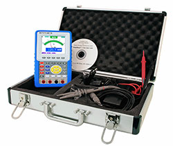
The handheld oscilloscope is delivered with a carrying case so the equipment and accessories are well kept. This case will make transportation easier therefore this handheld oscilloscope is ideal portable device. As the handheld oscilloscope offers multiple functions, you do not have to use different equipment, thus this device will be enough. For continuous measurements, the handheld oscilloscope can be powered through network component. For mobile work, the handheld oscilloscope has a lithium-ion battery. |
||
|
|
|||
|
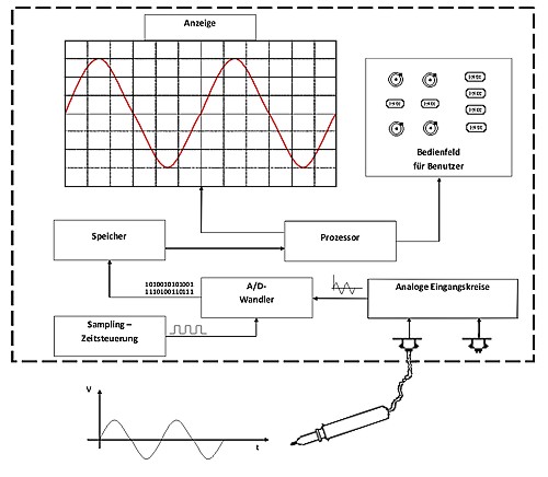
Operating principle of the digital oscilloscope with memory |
|||
|
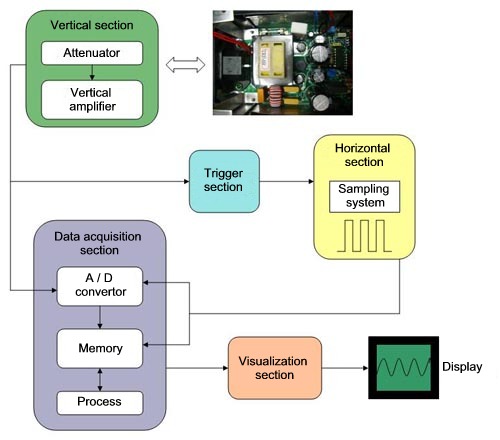
Oscilloscopes are used whenever it is necessary to represent electrical signals visually. The course of the tension is represented over time in a two dimensional coordinate system. A digital oscilloscope with memory is composed as follows:
The signal collected by the probe tip is set with the help of the analogue input circuits (signal, amplifier, etc). Then, it is sent to A/D transducer. The A/D transducer is a piece that transforms the analogue input voltage into a digital numerical value. The signal is checked at a fixed cycle. Values are stored in a memory. By means of a processor, values are read and displayed. |
|||
| Some concepts of the oscilloscope | |||
|
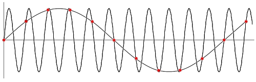
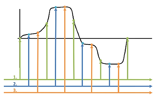
Speed of sampling: The sampling speed indicates how many times you check or measure the analogue signal. Usually it indicates the amount of collected samples per second, eg 500 MS/s (megasamples per second). It depends on the sampling speed how far a correct indication of the frequency of the input signal is shown. For a good presentation, the sampling speed should be ten times maximum of input frequency.
Red dots indicate the sampling. From this, a low frequency signal is reconstructed erroneously. To prevent this, use a low pass filter which filters out frequencies that are above the sampling frequency average.
This allows us to reconstruct the signal accurately, despite having a low sampling rate. This process has the disadvantage that the signal must be periodic and repetitive. Unique and brief events cannot be registered. |
|||
| ISO calibration certificate | |||
|
You can order this device with an ISO calibration certificate. The certificate is issued with your name and certifies the accuracy of the meter. Calibration is done according to ISO 9000. This means that all magnitudes are traceable to standards ENAC (National Accreditation Entity). You can find more information about the calibration here: |
|||
| Operating principle of the digital oscilloscope | |||
|
When you have a circuit and we observe the response of the resulting signal, a probe must be connected to the item you want to check to see the result of that circuit or component. The signal will go from the probe to the vertical section, which we can amplify or attenuate thanks to digital controls available in the oscilloscope. Once we have the amplified signal thanks to the previous module it is sent to the horizontal section so that through this step and the previous one, and thanks also to the different processes such as A/D, the display shows the signal we sought. If the voltage of this signal is positive with reference to the reference point or GND it is shown on the top of the screen, and if it is negative it will be displayed on the bottom. - Amp. Command (attenuation or amplification) - with this knob, the amplitude of the signal or signals are adjusted depending on the oscilloscope available. It is desirable that the signal occupies the entire screen without exceeding the limits of it. The digital oscilloscope, apart from these settings, usually has a memory to perform extended sets of readings, and to download data to a PC.
|
|||
| Ohm law | |||
|
George Simon Ohm was a German physicist known for his research on electrical currents. The formulation of the relationship between the intensity of current, potential difference and resistance contributes to Ohm law, which says that the amount of current flowing through a circuit formed by pure resistances is directly proportional to electromotive force applied to a circuit, and inversely proportional to the total circuit resistance. This law is usually expressed with the formula I = V/R, where I represents the intensity of the current measured in amperes, V is electromotive force in volts and R is the resistance in ohms. |
|||
| What is a series circuit? | |||
|
A circuit is one in which the devices or circuit elements are arranged so that all the current passes through each element without division or deviation in parallel circuits. |
|||
| Electric circuit | |||
|
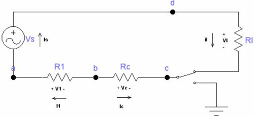
With an oscilloscope, you can check an electrical circuit. An electrical circuit is a series of electrical or electronic components such as resistors, inductors, capacitors, semiconductor electronic devices, etc. which are electrically connected together to generate, transport or modify electrical or electronic signals. It is said that a circuit is solved when you have determined the voltage and current through each element. Ohm law (as described above) is an important equation to determine the solution. However, this law may not be sufficient to provide a complete solution. As we see in the image that follows, it is necessary to use Kirchhoff laws to solve this circuit and most circuits.
As it can be seen here, the variables of currents are marked with and also the voltages associated with each resistor and the current associated with the voltage source (the marking includes the polarities of reference). The terminal point indicators are the beginning and end points of a single circuit element. A node is a point where two or more circuit elements meet. As discussed below, it is necessary to identify nodes to use the current law of Kirchhoff. In the picture above the nodes are a, b, c and d. D node connects the battery with the focus and essentially it extends across the top of the diagram, although we use a single point for convenience. The dots on each side of the switch indicate their terminals, but it is only necessary to represent one node, so only a node is indicated as c. For the circuit shown in the picture above we can identify seven incognita: ls, l1, lc, il, V1, Vc and VI. It is recalled that Vs voltage is a known voltage, because it represents the sum of the voltages between the terminals of the two dry cells, a constant voltage of 3 V. The problem is to find the seven incognita. In algebra, we know that to find n unknown quantities, you must solve n independent simultaneous equations. From Ohm law, it is known that three of the necessary equations are: V1 = I1 x R1/Vc = lc x Rc/Vl = il x Rl. These restrictions are known as Kirchhoff laws, named after Gustav Kirchhoff, who was the first to establish them in an article published in 1948. The 2 laws establishing mathematical restrictions are known as Kirchhoff law of current and Kirchhoff law voltage. - Node A --> Is - l1 = 0 (Equation 1.5) Note that equations 1.5 - 1.6 - 1.7 -1.8 are not an independent system because any of the four can be obtained from the other three. In any circuit with n nodes, you can derive n - 1 independent current equations of the Kirchhoff current law. If you do not see the Equation 1.8 we have 6 independent equations, ie equations from 1.2 to 1.7. One more is also required, we can get it from the Kirchhoff voltage law.
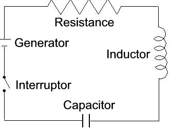
In the picture above we see an electric circuit, simple but complete, having three main parts: a switch which turns on or off the circuit, a power source, in this case the cell or battery, and finally an application, in this case a resistor or inductor and capacitor. |
|||
 |
 |
||
| Here you will find all the measuring instruments available at PCE Instruments. | |||
|
Contact: |
Contact: |
||