|
|
|
- Contact
us Other instruments: - Measures
-
Scales |


|
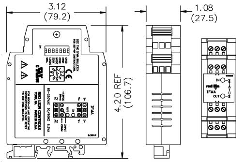
IFMA signal converter: frequency / analog signal |
|
|
The IFMA signal converter measures frequency / analog signals and processes and transforms an input frequency from 0 ... 1 Hz to 0 ... 25 kHz into an analog signal. The IFMA signal converter can be easily programmed and controlled by means of a 7-terminal DIP switch, a round BCD switch, a sensing device and two LED. The IFMA signal converter is simply slid in a C-rail or on mounting rails. There are two versions of the IFMA signal converter: This link shows an overview of all the signal converters we have available to meet your needs. |
|
|
- transforms an input frequency range into an |
|
| Technical specifications | |
| Inputs |
All standard sensors (PNP, NPN, permanent magnet, relay, CMOS or TTL) can be adapted through the three DIP switches. |
| Outputs |
Voltage: 0 ... 10 VDC o 0 ... 5 VDC / 10 mA, Current: 0 ... 20 mA o 4 ... 20 mA |
| Measurement principle | Continuous measurement in periods |
| Frequency range |
0 ... 1 Hz to 0 ... 25 kHz adjustable introducing a signal or with BCD switch. |
| Response time | Adjustable: 5 ms + 1 period at 10 s + 1 per. |
| Resolution | Voltage: 3,5 mV min Current: 5 µA min |
| Accuracy |
0.1 % of the operating range |
| Display |
- Lighted red LED with active output |
| Power supply | 9 ... 32 VDC (IFMA 1 signal converter) 85 ... 250 VAC (IFMA 2 signal converter) |
| Sensor power supply | only AC version: + 12 VDC 25 %, max. 60 mA |
| Temperature | operating 0 ...+ 50 °C / storage: - 40 ...+ 80 °C |
| Electromagnetic tolerance |
- disturbing emissivity: EN50081-2 |
| Connections | with screw clips |
| Case | Plastic case |
| Insulation |
2.2 kV between power input and output. 500 V in a minute. |
| Mounting | on C-rail or mounting rails. |
| Dimensions | 28 x 107 x 79 mm |
| Approvals |
UL (Underwriters Laboratories) for USA and Canada |
| Weight | 170 g |
| Sketch | |
|
|
|
|
Delivery contents |
|
 |
 |
|
Here you will find all the measuring instruments available at PCE Instruments. |
|
|
Contact: |
Contact: |

|
Below you will find an overview of the different product groups of measuring instruments |
||||||||||||||||||||||||
|
|
|
|
|||||||||||||||||||||