|
|
|
- Contact
us Other instruments: - Measures
-
Scales |


|
SR12-MTDC Logic module |
|
|
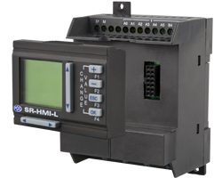
The SR12-MTDC Logic module is an user-friendly programming controller. The internal memory of the SR12-MTDC logic module can store the programmed electrical diagram. In addition to logic functions, the SR12-MTDC logic module offers counters and up to 128 time-controlled events. The programs for this logic module can have up to 128 blocks. Binary signals such as light barriers, probes, door contacts or a trip switch can be checked in its eight inputs. Six inputs can be used as analog inputs which allow the checking of sensors. This feature enables the SR12-MTDC logic module to be used for example, for temperature controls. The four available outputs are NPN transistor type and can switch up to a maximum of 2 A. Current date an time can be read thanks to the built-in internal clock which stores more than 80 hours (3 days). The optional LCD display of the SR12-MTDC logic module shows alarm warnings, counters condition as well as measured values. The program is performed with the help of the built-in electrical diagram. The simulation mode allows the user to check the program before downloading it into the SR12-MTDC logic module. The SR12-MTDC Logic module can be activated / deactivated via the software. Here you will find an overview of all Logic modules available at PCE-Instruments. |
|
|
View or print user's manual of the SR12-MTDC logic module |
|
|
- Program memory: 65 k |
 |
| Technical specifications | |
|
Power supply |
12 ... 24 V DC |
|
Inputs |
8 Inputs (A0 - A5, B4 - B5) 24 V DC <5 V >10 V |
|
Outputs |
4 x NPN transistors 24 V DC 2 A |
|
Real time clock |
80 hours Max. 5 seconds / days |
|
Protection |
IP 20
|
|
Program memory |
64 k |
|
Max. block functions |
128 |
|
Temperature |
-40 ... +70 ªC 0 ... +55 ºC |
|
Software |
|
|
|
|
|
|
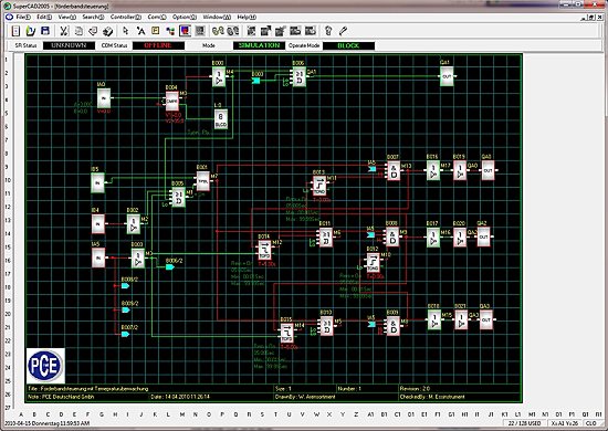
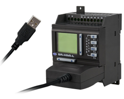
The SR12-MTDC logic module programs are carried out by the SuperCAD software and transferred through the USB port. Programs stored in the SR12-MTDC logic module can also be read. Programming is performed by an electrical diagram. During the development phase the simulation, which is built-in in the software, is a great help. It allows a function simulation before starting up the SR12-MTDC logic module. This will save you time and money in the subsequent search for software errors, due to the fact that such errors are excluded. |
|
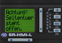
The interface between the user and the instrument is a LCD display. Here you will see measurement values, the counters condition as well as inputs and outputs. Single error messages can also be generated The user can have access to the process with the keys Esto permite delegar ciertas funciones al personal que utilizará el módulo lógico. Since the display can be removed, you can avoid tampering by unauthorized personnel. A LCD backlight display display can be ordered as an option. |
 |
|
Delivery contents |
|
| Optional accessories - SR-HMI LCD display - USB SR-DUSB connection cable -SP-24AL mains component - SR-20ETD I/O expansion module (12 Inputs, 8 outputs) |
|
 |
 |
| Here you will find an overview of all the measuring instruments available at PCE Instruments. | |
|
Contact: |
Contact: |
|
This page in German |
|

|
Below you will find an overview of the different product groups of measuring instruments |
||||||||||||||||||||||||
|
|
|
|
|||||||||||||||||||||